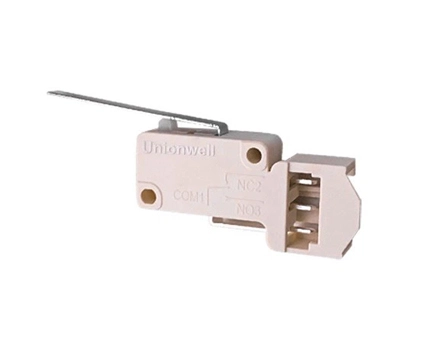
Robot vacuum cleaners rely on more than navigation software and distance sensors. Inside the chassis, compact mechanical components are also required to detect changes in wheel position and help the control system respond when the cleaner moves across uneven floors, thresholds, or raised surfaces.
One component used for this purpose is a basic micro switch installed near the drive-wheel mechanism. In the application described by Unionwell, one switch is positioned on each side of the drive system to detect whether the corresponding wheel remains in its normal operating position or has been lifted from the floor.
Although the switch is small, its operating force, actuator shape, and mounting position can directly affect the consistency of wheel detection.
Why Robot Vacuum Cleaners Need Wheel-Position Detection
A typical robot vacuum cleaner contains several integrated systems:
Drive motors and wheels
Main and side brushes
Vacuum and dust-collection components
Floor and obstacle sensors
Charging and docking components
Electronic control boards
Wheel-position detection mechanisms
The two drive wheels allow the cleaner to move forward, reverse, and turn. In many designs, each wheel is connected to a movable or spring-loaded structure that lets it adapt to changes in floor height.
When one wheel moves upward or loses normal contact with the floor, the control system needs a clear status signal. This allows the machine to carry out the response defined by its software, such as stopping the wheel, changing direction, or entering a protective operating routine.
How the Micro Switch Detects Wheel Movement
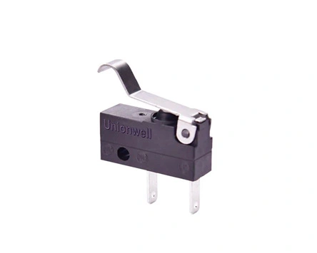
A micro switch with lever can be positioned so that its actuator remains in contact with the moving wheel assembly.
During normal operation, the wheel mechanism holds the actuator at a predetermined position. When the wheel is raised, the mechanical relationship changes, and the actuator is either pressed or released. The switch contacts then change state and send an electrical signal to the robot’s control board.
The detection sequence can be summarized as follows:
The drive wheel remains in its normal working position.
The wheel structure holds the switch actuator in a defined state.
The wheel moves upward after encountering a height difference or losing floor contact.
The actuator position changes.
The switch generates an ON/OFF status signal.
The controller carries out the programmed response.
This mechanical detection method is relatively straightforward and can be integrated without requiring a complex sensing structure.
Why a Snap-Action Mechanism Is Useful
A snap action switch changes its contact state rapidly after the actuator reaches a defined operating point.
This characteristic is useful in a robot vacuum cleaner because the wheel mechanism may move slowly or vibrate slightly as the cleaner passes across uneven flooring. A snap-action structure helps provide a more distinct electrical transition instead of allowing the contact state to change gradually.
However, the switch alone does not determine the quality of detection. Stable operation also depends on:
Correct mounting position
Sufficient actuator travel
Appropriate operating force
Controlled mechanical overtravel
Consistent wheel-assembly dimensions
Proper electrical signal processing
The switch and wheel module should therefore be evaluated as one integrated detection system.
Why the Unionwell G10 Series Fits Compact Wheel Modules
Unionwell’s G10 series is a compact switch platform offering optional levers and terminal configurations. Its small structure makes it suitable for consideration in home appliances and industrial control equipment where internal installation space is limited.
For a robot vacuum project, the G10 configuration should be selected according to the actual wheel design rather than the series name alone.
Important selection factors include:
Selection factor
Engineering consideration
Switch dimensions
Must fit beside the wheel and motor assembly
Actuator type
Must match the direction of wheel movement
Operating force
Should not restrict normal suspension movement
Operating position
Must correspond to the required detection point
Pre-travel
Affects when the switch changes state
Overtravel
Prevents excessive mechanical loading
Contact configuration
Must match the controller input circuit
Terminal direction
Should support efficient wiring and assembly
Mechanical durability
Must support repeated wheel movement
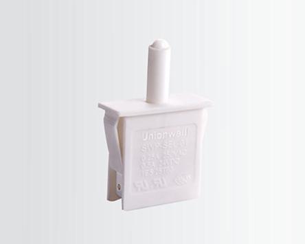
A pin-plunger version may be suitable when the wheel component moves directly toward the switch. A lever type micro switch may offer more installation tolerance when the motion is indirect or the available mounting position is offset.
Common Integration Problems
The switch operates too early
If the switch changes state before the wheel has moved far enough, the cleaner may report a lifted wheel during normal travel. The mounting position or actuator geometry should be adjusted.
The switch operates too late
Insufficient actuator travel may prevent the switch from detecting the wheel change consistently.
The wheel mechanism presses the switch excessively
Continuous excessive compression may place unnecessary stress on the actuator. The design should provide controlled overtravel.
The signal changes repeatedly
Mechanical vibration near the operating point may create an unstable signal. Engineers should review the mounting tolerance, actuator selection, and software filtering strategy.
Dust reaches the installation area
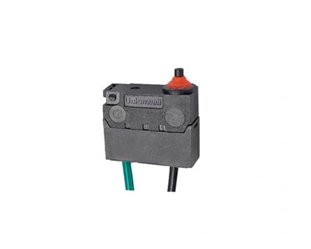
Robot vacuum cleaners operate around hair and dust. If the switch location presents a significant contamination risk, a sealed product configuration may need to be evaluated.
FAQ
What does a micro switch do in a robot vacuum cleaner?
It can detect a mechanical position change inside the cleaner. In the drive-wheel assembly, it may indicate whether a wheel is in its normal working position or has moved upward.
Is one switch required for each wheel?
The customer application material shows one micro switch on each of the two drive-wheel mechanisms. The final quantity depends on the cleaner’s mechanical and control design.
Which actuator should be selected?
The actuator should be chosen according to the direction, distance, and force of wheel movement. Pin plungers, straight levers, and other lever configurations may suit different structures.
Is a waterproof switch always necessary?
Not necessarily. The required protection depends on where the switch is installed and how effectively the cleaner housing isolates it from dust and moisture.
Factory Address:No. 9 Park Avenue, Longmen County, Huizhou City, Guangdong Province, China
+86-13431874643
We use cookies to offer you a better browsing experience, analyze site traffic and personalize content. By using this site, you agree to our use of cookies.
Visit our cookie policy to learn more.
 English
  français
  Deutsch
  Español
  italiano
  português
  tiếng việt
  Türkçe
  slovenský
  slovenčina
  беларускі
Global_Safety_Approvals_Basic_Micro_Switch_G5.webp "Global Safety Approvals Basic Micro Switch G5")