High-voltage DC contactors are widely used to connect and disconnect high-voltage circuits in electric vehicles, charging equipment, battery systems, and other new-energy applications.
The main contacts carry the power circuit, but the control system may also need to confirm whether the contactor’s internal mechanism has physically reached the required open or closed position. A compact micro switch can be incorporated into an auxiliary feedback structure to provide this mechanical status signal.
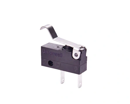
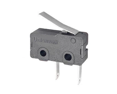
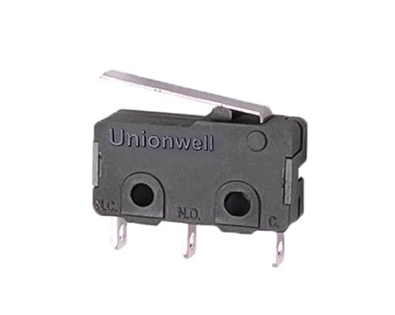
In the customer application information supplied to Unionwell, the G10 micro switch was evaluated as a position-detection component inside a high-voltage DC contactor.
What Happens Inside a High-Voltage DC Contactor?
A high-voltage DC contactor generally includes:
An electromagnetic operating mechanism
Main power contacts
Arc-control components
A movable armature or transmission mechanism
Coil and control terminals
Housing and insulation components
Optional auxiliary feedback contacts
When the coil receives a control signal, electromagnetic force moves the internal mechanism. This movement opens or closes the main contacts and changes the state of the high-voltage circuit.
The controller may issue a command to the coil, but a command alone does not always confirm that the mechanical mechanism has completed the required movement. Auxiliary position detection helps provide additional status information.
The Role of the Micro Switch
The micro switch is mounted so that a moving part of the contactor operates its actuator.
When the contactor mechanism reaches a defined position, the actuator is pressed or released, and the switch contacts change state. The resulting signal can be transmitted to a monitoring or control circuit.
Depending on the contactor design, this feedback may be used to:
Confirm that the mechanism has reached the closed position
Confirm that the mechanism has returned to the open position
Support operating-status monitoring
Assist with fault diagnosis
Coordinate system-control sequences
Identify incomplete mechanical movement
The micro switch normally works in the auxiliary signal circuit. It should not be described as the component directly switching the main high-voltage load unless the electrical design specifically confirms this.
Why Snap-Action Switching Matters
A contactor mechanism moves through a defined mechanical stroke. The feedback switch needs to change contact state at a repeatable point within this movement.
A snap action switch can provide a rapid contact transition when the actuator reaches its operating position. This helps generate a clear electrical signal even when the mechanical component moves relatively slowly.
For contactor feedback applications, the switch should offer:
Repeatable operating position
Stable release position
Suitable differential movement
Low and consistent operating force
Compact dimensions
Appropriate contact configuration
Reliable performance during repeated cycles
A switch with excessive operating force may affect the mechanical movement of a small auxiliary linkage. A switch with insufficient actuator travel may fail to change state consistently.
Key Engineering Parameters
Parameter
Why it matters
Operating position
Determines when the feedback signal changes
Release position
Confirms when the mechanism returns
Operating force
Should not interfere with contactor movement
Differential movement
Influences signal stability around the operating point
Actuator shape
Must match the internal mechanical interface
Contact form
Must suit the monitoring circuit
Electrical rating
Must match the auxiliary load
Temperature range
Must suit the contactor’s internal conditions
Vibration resistance
Important in vehicle and charging applications
Mechanical life
Must support repeated contactor cycles
A small micro switch may be preferred because the auxiliary detection structure is normally located within a space already occupied by the coil, contacts, insulation barriers, and arc-control components.
Applications in New-Energy Systems
The customer application material identifies high-voltage DC contactors as components used in new-energy vehicles and charging stations. The exact number and arrangement of contactors vary according to the vehicle, charging architecture, and power-system design.
Typical positions may include:
Main battery connection
Pre-charge circuit
Fast-charging circuit
Normal charging circuit
High-voltage auxiliary circuit
Energy-storage power path
Micro-switch selection should be based on the specific auxiliary mechanism inside each contactor. The overall voltage of the power system does not automatically determine the electrical rating of the feedback switch because the auxiliary circuit may operate at a different voltage and current.
Potential Design Problems
Feedback changes before the main mechanism reaches position
The switch may be mounted too close to the beginning of the mechanical stroke. Its operating point should be aligned with the contactor’s actual status requirement.
The switch does not release correctly
The mechanism may not provide enough return travel, or the switch may remain excessively compressed.
Feedback becomes unstable under vibration
The actuator may be positioned too close to the switch’s operating threshold. Mechanical tolerance and differential movement should be reviewed.
The switch restricts the contactor mechanism
The operating force may be too high, or the linkage may apply force at an unsuitable angle.
Batch variation affects assembly
The contactor manufacturer should define allowable tolerances for the switch position, actuator dimensions, and mounting structure.
Validation for Contactor Manufacturers
Before approving the switch for mass production, manufacturers should test it within the complete contactor assembly.
Recommended evaluation items include:
Open-position feedback
Closed-position feedback
Operating and release consistency
Repeated contactor cycling
Temperature testing
Vibration testing
Electrical contact stability
Assembly-tolerance verification
Terminal or wire retention
Interaction with the internal moving mechanism
Testing the individual switch is not sufficient because final performance depends on the entire mechanical interface.
Conclusion
A micro switch can provide direct mechanical position feedback inside a high-voltage DC contactor. Its role is not to replace the main contacts but to help the controller identify whether the internal operating mechanism has reached the required position.
For new-energy and industrial-control projects, Unionwell can evaluate the application according to the available mounting space, actuator movement, operating force, auxiliary circuit, and validation requirements. Submit the contactor drawing and switch operating conditions to request a suitable snap action switch solution and engineering sample.
FAQ
Does the micro switch carry the main high-voltage current?
Normally, the switch in this application is used for auxiliary position feedback. Its electrical load should be confirmed from the actual contactor circuit.
What does the feedback signal indicate?
It can indicate that the contactor mechanism has reached a predefined open or closed position.
Why is operating force important?
Excessive operating force may interfere with the contactor mechanism, while an unsuitable low-force design may not provide the required mechanical stability.
Can the actuator or terminal be customized?
Available actuator, terminal, and wire options depend on the selected switch platform and project requirements. Any customized configuration should be validated in the complete contactor assembly.
Factory Address:No. 9 Park Avenue, Longmen County, Huizhou City, Guangdong Province, China
+86-13431874643
We use cookies to offer you a better browsing experience, analyze site traffic and personalize content. By using this site, you agree to our use of cookies.
Visit our cookie policy to learn more.
 English
  français
  Deutsch
  Español
  italiano
  português
  tiếng việt
  Türkçe
  slovenský
  slovenčina
  беларускі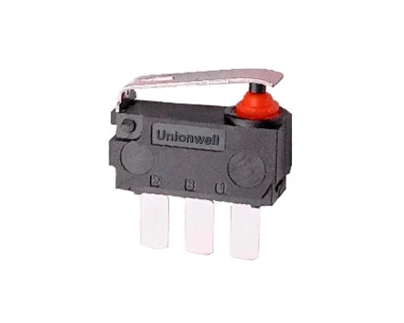
Global_Safety_Approvals_Basic_Micro_Switch_G5.webp "Global Safety Approvals Basic Micro Switch G5")